Difference between revisions of "InterfaceRoomba"
Carlosrhrh (talk | contribs) (→Introducction) |
Carlosrhrh (talk | contribs) (→schematic and description) |
||
| Line 25: | Line 25: | ||
[[Image:interface_roomba.jpg|center|800px]] | [[Image:interface_roomba.jpg|center|800px]] | ||
| − | In the interface, the chip | + | In the interface, the chip FT232RL is the main component. The FT232RL is a USB to serial UART interface with optional clock generator output, an integrated Clock Circuit, an integrated EEPROM, etc… |
| − | This interface is | + | This interface is built in a Bus Powered Configuration (see Device Configurations on PDF), in order to get its power from the PC. |
| − | The pin RTS# is connected with the pin DD (Device Detect) and | + | The pin RTS# is connected with the pin DD (Device Detect) and this pin is put on a high level (5V) when the interface is started, to be able to start the communication between the PC and the BOT . |
| − | The FT232RL | + | The FT232RL has a configurable CBUS I/O Pin Options, in which CBUS0 has a default configuration of TXLED# for pulsing a LED upon transmission of data, and CBUS1 has a default configuration of RXLED# for pulsing a LED upon receiving data. (See LED Interface on PDF). The value of led’s resistors depends on the D.C. Forward Current of the leds. |
| − | This interface also contains a voltage regulator circuit to get power to the KINET from the BOT. The input voltage of this regulator is VBAT (14.4V) and the output 12V, but when the ROOMBA is charging the input up until more than 19V, for this way | + | This interface also contains a voltage regulator circuit to get power to the KINET from the BOT. The input voltage of this regulator is VBAT (14.4V) and the output 12V, but when the ROOMBA is charging the input up until more than 19V, for this way it is necessary using an appropriate heat sinks for this device. |
PDF FT232RL: [http://pdf1.alldatasheet.es/datasheet-pdf/view/144591/FTDI/FT232RL.html] | PDF FT232RL: [http://pdf1.alldatasheet.es/datasheet-pdf/view/144591/FTDI/FT232RL.html] | ||
Revision as of 11:10, 22 October 2013
- Project Name: Interface Roomba
- Authors: Carlos
- Academic Year: 2012-2013
- Degree: graduate
- Tags: MYRA, Turtlebot,
- State: Developing
- Source License: GPLv3
- Document License:
Contents
Introduction
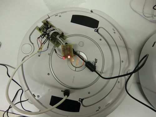
In this document, it is shown an interface to conect a Roomba vacuum with a PC and a circuit added to it in order to supply power from Roomba to a Kinet camera.
schematic and description
In the interface, the chip FT232RL is the main component. The FT232RL is a USB to serial UART interface with optional clock generator output, an integrated Clock Circuit, an integrated EEPROM, etc… This interface is built in a Bus Powered Configuration (see Device Configurations on PDF), in order to get its power from the PC. The pin RTS# is connected with the pin DD (Device Detect) and this pin is put on a high level (5V) when the interface is started, to be able to start the communication between the PC and the BOT . The FT232RL has a configurable CBUS I/O Pin Options, in which CBUS0 has a default configuration of TXLED# for pulsing a LED upon transmission of data, and CBUS1 has a default configuration of RXLED# for pulsing a LED upon receiving data. (See LED Interface on PDF). The value of led’s resistors depends on the D.C. Forward Current of the leds. This interface also contains a voltage regulator circuit to get power to the KINET from the BOT. The input voltage of this regulator is VBAT (14.4V) and the output 12V, but when the ROOMBA is charging the input up until more than 19V, for this way it is necessary using an appropriate heat sinks for this device.
PDF FT232RL: [1]
Roomba conections
In this figure we can see a pin description of the Roomba DIN conector.


