MYRAbot's arm control (bioloid+arduino)
Contents
Bioloid arm
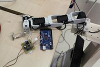
The arm that we will use is that Carlos Rodríguez Hernández developed in the project MYRA Robot: Hardware Update . The main components are:

- Arduino mega 2560 board.
- 74LS241 chip (tree-state Buffer).
- Voltage regulator circuit.
- 5 serial servo motors Dynamixel AX-12A.
- Mounting components of Bioloid kit.
- Parts made for the gripper and to fix to MYRAbot.
Arduino IDE and rosserial
For the communication among arduino and ROS, we install arduino IDE and rosserial (package de ROS which include the package rosserial_arduino with the libraries for arduino. We will start to installing arduino IDE, for this, we will execute the next commands in a terminal:
sudo apt-get update
sudo apt-get install arduino arduino-core
When the installation of arduino software ends, we will install the ROS package. For this, we will execute the next command in a terminal:
sudo apt-get install ros-ROS_DISTRO-rosserialWhen we will have installed arduino IDE and the stack rosserial, we must copy the libraries for the package rosserial_arduino to the sketchbook of arduino. For this, we will execute the next commands in a terminal:
roscd rosserial_arduino/libraries
cp -r ros_lib /home/”SESSION_NAME”/sketchbook/libraries/ros_lib
Creating a package for our programs
Previously, we must have created a workspace for our ROS distribution. We will create a package in order to compile and send our programs to arduino board. We will make a package named "arduino_fer" with the the necessary dependences for our programs, for this, we will execute the next commands in a terminal:
cd ~/ros_workspace
roscreate-pkg arduino_fer rosserial_arduino std_msgs
We must change the content of the file "CMakeLists.txt" of our package for the next lines:
cmake_minimum_required(VERSION 2.4.6)
include($ENV{ROS_ROOT}/core/rosbuild/rosbuild.cmake)

rosbuild_find_ros_package(rosserial_arduino)
include(${rosserial_arduino_PACKAGE_PATH}/cmake_scripts/rosserial.cmake)
We will execute the next commands in a terminal in order to finalize the creation of the package:
roscd arduino_fer
cmake .
First program (To whole power)
We will make the first program that publishes a topic named "cifra" and subscribe a topic named "resultado". When we publish a number in the topic "cifra" the program multiplies the number by itself and publishes the result in the topic "resultado". The code of the program is shown below:
#include <ros.h>
#include <std_msgs/Int16.h>

ros::NodeHandle nh;
int pot;

void potencia( const std_msgs::Int16& cifra){

::pot = cifra.data*cifra.data;
}

ros::Subscriber<std_msgs::Int16> sub("cifra", &potencia );
std_msgs::Int16 res;

ros::Publisher pub("resultado", &res);

void setup()
{
  nh.initNode();
  nh.subscribe(sub);
  nh.advertise(pub);
}

void loop()
{
  res.data = ::pot;
  pub.publish( &res );
  nh.spinOnce();
  delay(1000);
}
We must add to the file "CMakeLists.txt" the lines indicated below in order in order to compile the program and send to arduino board:
set(FIRMWARE_NAME potencia)

set(${FIRMWARE_NAME}_BOARD MODELO_NUESTRA_PLACA)   # Model of arduino board
set(${FIRMWARE_NAME}_SRCS src/potencia.cpp )
set(${FIRMWARE_NAME}_PORT /dev/ttyACM0)            # Serial port to upload
generate_ros_firmware(${FIRMWARE_NAME})
Here is set the name for the program, type of arduino board (uno, atmega328 o mega2560), name and address of the file, and serial port of the PC used to communicate with the board. We have to execute the next commands in a terminal:
roscd arduino_fer
make potencia-upload
We must launch the ROS core in a terminal in order to allow the execution of the program, if it is not already launched. We will execute the next command in a terminal:
roscoreIn other terminal, we will execute the node that communicates ROS with the arduino board, we set the port that is used to communication. In order to know the port that is used, we can see the port used in the menu "Tools">"Serial port" of the software arduino IDE, the board must be plugged. In this case the port is "ttyACM0".
rosrun rosserial_python serial_node.py /dev/ttyACM0We will execute in other terminal the next command in order to publish a number in the topic "cifra":
rostopic pub cifra std_msgs/Int16 NUMBER --onceWe will execute in other terminal the next command in order to test that the program calculates the square of the published number in the topic "cifra" and publishes the result in the topic "resultado":
rostopic echo resultadoArduino and servo motors Dinamixel
In Savage Electronics we can find the hardware adaptations to communicate the arduino mega 2560 board with the servo motors Dynamixel AX-12A of ROBOTICS. Here also we can find the libraries for programming (DynamixelSerial).
Second program (Move)
This program is a test of the communications between arduino mega 2560 board and servo motor Dynamixel AX-12A. The program publishes the topic "angulo" which contains the position of the servo motor (between 0 and 1023) and subscribes the topic "giro" which receives the goal position (between 0 and 1023). The servo motor will move with a constant velocity of 128 (Integer between 0 and 1023). The code of the program is shown below:
#include <ros.h>
#include <std_msgs/Int16.h>
#include <DynamixelSerial1.h>

ros::NodeHandle nh;


void mover( const std_msgs::Int16& giro){

  Dynamixel.moveSpeed(1,giro.data,128);

}

ros::Subscriber<std_msgs::Int16> sub("giro", &mover );

std_msgs::Int16 ang;
ros::Publisher pub("angulo", &ang);

void setup()
{
  nh.initNode();
  nh.subscribe(sub);
  nh.advertise(pub);
  Dynamixel.begin(1000000,2);
  delay(1000);
}

void loop()
{
  int posicion = Dynamixel.readPosition(1);
  ang.data = posicion;
  pub.publish( &ang );
  nh.spinOnce();
  delay(10);
}
We can't use the previously made package in order to compile and send the program to the arduino board. We must use the arduino IDE software due to that we use a external library to ROS system. When the program was uploaded we will execute the next command in a terminal, to launch the core system:
roscoreWe will execute the next command in other terminal in order to launch the communication node ROS-arduino:
rosrun rosserial_python serial_node.py /dev/ttyACM0We will execute the next command in other terminal in order to publish the goal position of the servo motor in the topic "giro":
rostopic pub giro std_msgs/Int16 GOAL_POSITION --onceThe servo motor will immediately move to the goal position. We can execute the next command in other terminal in order to see the position value of the servo motor at any time:
rostopic echo anguloArm's kinematics model
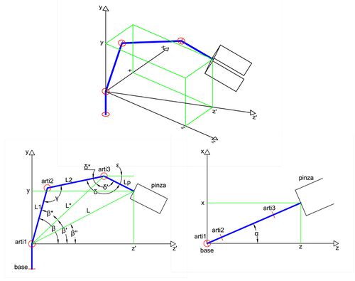
We need to know the spatial position of the arm for the correct placement of the gripper. The position depends on the position angle of the servo motors (direct kinematics). We know the goal point and we must obtain the position angle of the servo motors to achieve it (inverse kinematics). The arm have 5 joints (1 to open-close gripper) and all work in the same plane, for this reason we don't need use the Denavit-Hartenberg parameters.
Inverse kinematic
We use the diagram shown above to obtain the inverse kinematics. Where x, y and z are the goal point coordinates, and ε is the angle that the gripper forms with x-z plane. The obtained equations are shown below:
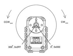
We have to calculate the value of position angle for the servo motors Dynamixel AX-12A according its turn limits (1023 positions throughout 300º):

 We add 150º from the position angle in order to set the 0º coincident with z axis.
 We add 60º from the position angle in order to set the 0º coincident with z axis.
 We subtract 30º from the position angle in order to set the 0º coincident with the longitudinal axis of servo motor.
 We subtract 30º from the position angle in order to set the 0º coincident with the longitudinal axis of servo motor.
Direct kinematics
We can use the previous equations to obtain the placement point through the position angle of the servo motors. The equations are shown below:
Arm workspace and boundaries
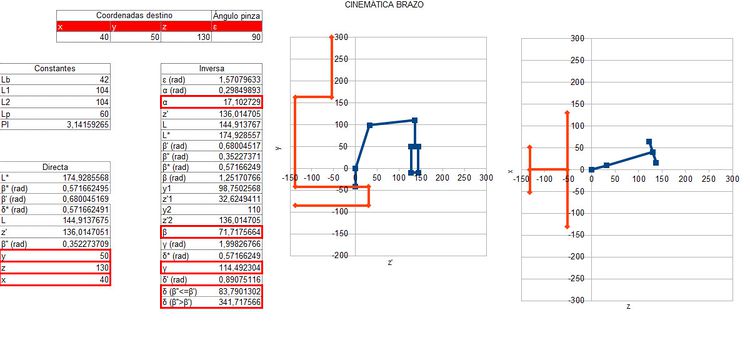
We need to set the boundaries of the position angles of the servo motors to avoid self collisions and collision with other parts of MYRAbot. We have made a spreadsheet using the equations for inverse and direct kinematics. The spreadsheet shows the spacial placement of the arm in two dispersion graphs.

Control programs
Third program (Came here)
We place a interface program in arduino board that communicates the servo motor with the control programs in ROS. We need publish and subscribe the data of 5 servo motors so we will create own messages.
Creating custom messages in ROS
First, we will create a new package with the necessary dependences for our programs (std_msgs geometry_msgs roscpp). We will create a folder named "msg" within the created package, here we place the next description files for our messages (data type and field name).
We will create the basis message that contains the data for each servo motor. We will create a file named "Servos.msg" with the content that is shown below:
int16 base
int16 arti1
int16 arti2
int16 arti3
int16 pinza
We will use the previous message in order to define the data type. We will create a file named "WriteServos.msg" to send data to the servo motors (position, velocity and torque) with the content that is shown below:
Servos posicion
Servos velocidad
Servos par
We will create a file named "ReadServos.msg" in order to receive data to the servo motors (position, status and current) with the content that is shown below:
Servos posicion
Servos estado
Servos corriente
We have to edit the file "CMakeLists.tx" in our package in order to allow the creation the ROS messages. We will delete the symbol "#" in the line that is shown below:
# rosbuild_gensrv()We will execute the next commands in a terminal in order to compile and create the messages, where "brazo_fer" is the name of the created package:
roscd brazo_fer
make
We will execute the next command in a terminal in order to add this messages to the arduino libraries in "rosserial":
rosrun rosserial_client make_library.py ~/sketchbook/libraries brazo_ferArduino program
The program for arduino board subscribes the topic "move_arm" which receives the orders for the servo motors and publishes the "topic" "pose_arm" which sends the servo motors information. The code of the program is shown below:
#include <ros.h>
#include <brazo_fer/Servos.h>
#include <brazo_fer/WriteServos.h>
#include <brazo_fer/ReadServos.h>
#include <std_msgs/Bool.h>
#include <math.h>

#include <DynamixelSerial1.h>

ros::NodeHandle nh;

void mover(const brazo_fer::WriteServos& brazo){

  brazo_fer::Servos par = brazo.par;

  brazo_fer::Servos vel = brazo.velocidad;

  brazo_fer::Servos move = brazo.posicion;

  int posicion[4];

  if (par.base == 0){
    Dynamixel.torqueStatus(1,OFF);
  }
  else {
    Dynamixel.torqueStatus(1,ON);

    Dynamixel.moveSpeed(1,move.base,vel.base);
  }

  if (par.arti1 == 0){
    Dynamixel.torqueStatus(2,OFF);
  }
  else {
    Dynamixel.torqueStatus(2,ON);

    Dynamixel.moveSpeed(2,move.arti1,vel.arti1);
  }

  if (par.arti2 == 0){
    Dynamixel.torqueStatus(3,OFF);
  }
  else {
    Dynamixel.torqueStatus(3,ON);

    Dynamixel.moveSpeed(3,move.arti2,vel.arti2);
  }

  if (par.arti3 == 0){
    Dynamixel.torqueStatus(4,OFF);
  }
  else {
    Dynamixel.torqueStatus(4,ON);

    Dynamixel.moveSpeed(4,move.arti3,vel.arti3);
  }

}

void pinza(const brazo_fer::WriteServos& pinza){

  brazo_fer::Servos par = pinza.par;

  brazo_fer::Servos vel = pinza.velocidad;

  brazo_fer::Servos move = pinza.posicion;

  int posicion;

  if (par.pinza == 0){
    Dynamixel.torqueStatus(5,OFF);
  }
  else {
    Dynamixel.torqueStatus(5,ON);

    Dynamixel.moveSpeed(5,move.pinza,vel.pinza);
  }

}

ros::Subscriber<brazo_fer::WriteServos> move_sub("move_arm", &mover );
ros::Subscriber<brazo_fer::WriteServos> hand_sub("hand_arm", &pinza );

brazo_fer::ReadServos pec;
std_msgs::Bool pulsador;

ros::Publisher pose_pub("pose_arm", &pec);


void setup()
{
  nh.initNode();
  nh.subscribe(move_sub);
  nh.subscribe(hand_sub);
  nh.advertise(pose_pub);

  Dynamixel.begin(1000000,2);

}

void loop()
{
  brazo_fer::Servos pos;
  brazo_fer::Servos est;
  brazo_fer::Servos cor;

  pos.base = Dynamixel.readPosition(1);
  pos.arti1 = Dynamixel.readPosition(2);
  pos.arti2 = Dynamixel.readPosition(3);
  pos.arti3 = Dynamixel.readPosition(4);
  pos.pinza = Dynamixel.readPosition(5);

  est.base = Dynamixel.moving(1);
  est.arti1 = Dynamixel.moving(2);
  est.arti2 = Dynamixel.moving(3);
  est.arti3 = Dynamixel.moving(4);
  est.pinza = Dynamixel.moving(5);

  cor.base = Dynamixel.readLoad(1);
  cor.arti1 = Dynamixel.readLoad(2);
  cor.arti2 = Dynamixel.readLoad(3);
  cor.arti3 = Dynamixel.readLoad(4);
  cor.pinza = Dynamixel.readLoad(5);

  pec.posicion = pos;
  pec.estado = est;
  pec.corriente = cor;

  pose_pub.publish( &pec );

  nh.spinOnce();

}
We will use arduino IDE software to compile and send the program to the board. We will use this program for the next control programs since it is a interface between the servo motors and ROS system.
ROS program
This program uses the equations of the inverse kinematics to set the position angle of the servo motors in order to reach the goal point that is within the workspace. The program subscribe the topic "point" which receives the goal point, also it subscribes the topic "pose_arm" which receives the information of servo motors, and publish the topic' "move_arm" which indicates to the arduino program the position, velocity and torque of for the servo motors. We will create a file named "control_v01.cpp" with the content that is shown below within the folder "src" of our package:
  #include "ros/ros.h"
  #include "brazo_fer/Servos.h"
  #include "brazo_fer/WriteServos.h"
  #include "brazo_fer/ReadServos.h"
  #include "geometry_msgs/Point.h"
  #include "math.h"

  #define PI 3.14159265
  #define L1 104
  #define L2 104
  #define Lp 60


  brazo_fer::Servos move, vel, p, e, c;

  void posicion(const brazo_fer::ReadServos& pose)
  {

    ::p = pose.posicion;
    ::e = pose.estado;
    ::c = pose.corriente;

  }

  void punto(const geometry_msgs::Point& point)
  {
	ros::NodeHandle n;

  	ros::Publisher move_pub_=n.advertise<brazo_fer::WriteServos>("move_arm", 1);

  	double x = point.x;
  	double y = point.y;
	double z = point.z;

	y = y + z*tan(atan2(45,250));

	int coordenadas_correctas = 1;

	double alfa, beta, beta_a, beta_p, beta_pp, gamma, delta, delta_a, delta_p, epsilon;
	double z_p;
	double L_a, L;

	epsilon = 0;

	alfa = (atan2(x,z)*180)/PI;

	z_p = sqrt(pow(z,2)+pow(x,2));

	L = sqrt(pow(z_p,2)+pow(y,2));

	L_a = sqrt(pow(y+(Lp*sin(epsilon)),2)+pow(z_p-(Lp*cos(epsilon)),2));

	beta_p = atan2(y+(Lp*sin(epsilon)),z_p-(Lp*cos(epsilon)));

	beta_pp = atan2(y,z_p);

	beta_a = acos((pow(L1,2)+pow(L_a,2)-pow(L2,2))/(2*L1*L_a));

	beta = ((beta_p+beta_a)*180)/PI;

	gamma = acos((pow(L1,2)+pow(L2,2)-pow(L_a,2))/(2*L1*L2));

	delta_a = PI-(beta_a+gamma);

	gamma = (gamma*180)/PI;

        delta_p = acos((pow(L_a,2)+pow(Lp,2)-pow(L,2))/(2*L_a*Lp));

	if (beta_pp > beta_p) {
		delta = ((2*PI-(delta_p-delta_a))*180)/PI;
	}
	else {
		delta = ((delta_p+delta_a)*180)/PI;

		if (isnan(delta)) {
			delta = ((PI+delta_a)*180)/PI;
		}
	}

	if (isnan(gamma)) // si no hay solución
	{
		coordenadas_correctas = 0;
	}

	::move.base = ((alfa+150)*1023)/300;
	::move.arti1 = ((beta+60)*1023)/300;
	::move.arti2 = ((gamma-30)*1023)/300;
	::move.arti3 = ((delta-30)*1023)/300;
	::move.pinza = 511;

	::vel.base = abs(::move.base - ::p.base)/5;
	::vel.arti1 = abs(::move.arti1 - ::p.arti1)/5;
	::vel.arti2 = abs(::move.arti2 - ::p.arti2)/5;
	::vel.arti3 = abs(::move.arti3 - ::p.arti3)/5;
	::vel.pinza = abs(::move.pinza - ::p.pinza);

	if (coordenadas_correctas == 1 && (205 <= ::move.base && ::move.base <= 818) && (120 <= ::move.arti1 && ::move.arti1 <= 920) && ::move.arti2 >= 50  && ::move.arti3 <= 828) {

                brazo_fer::WriteServos mover;

                mover.posicion = ::move;

                mover.velocidad = ::vel;

		mover.par.base = 1;
		mover.par.arti1 = 1;
		mover.par.arti2 = 1;
		mover.par.arti3 = 1;
		mover.par.pinza = 1;

                move_pub_.publish(mover);
	}
	else {
		std::cout<<"Error, invalid coordinates or unattainable point"<<std::endl;
	}

  }


  int main(int argc, char **argv)
  {

	ros::init(argc, argv, "control_brazo");

	ros::NodeHandle n;


  	ros::Subscriber pose_sub_= n.subscribe("pose_arm", 1, posicion);

  	ros::Subscriber point_sub_= n.subscribe("point", 1, punto);

  	ros::Publisher move_pub_=n.advertise<brazo_fer::WriteServos>("move_arm", 1);


	ros::spin();

        return 0;
  }
We have to add the next line to the file "CMakeLists.txt" of our package in order to compile and create the executable file:
rosbuild_add_executable(contro_v01 src/control_v01.cpp)
We will execute the next commands in a terminal in order to compile and create the executable file:
roscd brazo_fer
make
Running the program
First we will execute the next command in a terminal in order to launch the ROS core, if it has not launched previously.
roscoreWe will execute the next command in other terminal in order to launch the communication node ROS-arduino:
rosrun rosserial_python serial_node.py /dev/ttyACM0We will execute the next command in a terminal in order to launch the control program:
rosrun brazo_fer control_v01We will execute the next command in a terminal in order to publish in the topic "point" the goal point:
rostopic pub point geometry_msgs/Point '{x: 50, y: 100, z: 150}' --onceThe arm will move to the goal point. We can see the arm moving from the start point to the goal point in the next video:


