Difference between revisions of "PCL/OpenNI tutorial 0: The very basics"
m |
m |
||
| (27 intermediate revisions by the same user not shown) | |||
| Line 5: | Line 5: | ||
| − | One of the most important fields of robotics is [ | + | One of the most important fields of robotics is [https://en.wikipedia.org/wiki/Computer_vision computer vision]. A machine that is able to "see" its environment can have a lot of applications. For example, think of a robot in a production line that grabs some parts and moves them somewhere else. Or a surveillance system that is able to recognize how many people are there in a room. Or a biped robot making its way through a room, evading obstacles such as tables, chairs or bystanders. |
| − | For many years, the most common sensors for computer vision were 2D cameras, that retrieved a RGB image of the scene (like all the digital cameras that are so common nowadays, in our laptops or smarphones). Algorithms exist that are able to find an object in a picture, even if it is rotated or scaled, or that can retrieve motion data from a stream of video, and even perform 3D analysis to track the camera's position. All these years' worth of research is now available in libraries like [ | + | For many years, the most common sensors for computer vision were 2D cameras, that retrieved a RGB image of the scene (like all the digital cameras that are so common nowadays, in our laptops or smarphones). Algorithms exist that are able to find an object in a picture, even if it is rotated or scaled, or that can retrieve motion data from a stream of video, and even perform 3D analysis to track the camera's position. All these years' worth of research is now available in libraries like [https://en.wikipedia.org/wiki/OpenCV OpenCV] (Open Source Computer Vision Library). |
3D sensors are available, too. The biggest advantage they offer is that it is trivial to get measurements about distances and motion, but the addition of a new dimension makes calculations expensive. Working with the data they retrieve is a lot different that working with a 2D image, and texture information is rarely used. | 3D sensors are available, too. The biggest advantage they offer is that it is trivial to get measurements about distances and motion, but the addition of a new dimension makes calculations expensive. Working with the data they retrieve is a lot different that working with a 2D image, and texture information is rarely used. | ||
| Line 19: | Line 19: | ||
==Stereo cameras== | ==Stereo cameras== | ||
| − | [ | + | [https://en.wikipedia.org/wiki/Computer_stereo_vision Stereo cameras] are the only passive measurement device of the list. They are essentially two identical cameras assembled together (some centimeters apart), that capture slightly different scenes. By computing the differences between both scenes, it is possible to infer depth information about the points in each image. |
| − | + | A stereo pair is cheap, but perhaps the least accurate sensor. Ideally, it would require perfect calibration of both cameras, which is unfeasible in practice. Bad light conditions will render it useless. Also, because of the way the algorithm works (detecting corresponding points of interest in both images), they give poor results with empty scenes or objects that have plain textures, with few interest points. Some models circumvent this by projecting a grid or texture of light on the scene (active stereo vision). | |
| − | + | I will not go into detail about the math involved with the triangulation process, as you can find it on the internet. | |
| + | |||
| + | |||
| + | [[Image:Stereo.png|thumb|center|200px|Example of stereo camera.]] | ||
| − | |||
==Time-of-flight== | ==Time-of-flight== | ||
| − | [ | + | [https://en.wikipedia.org/wiki/Time_of_flight Time-of-flight] (ToF) sensors work by measuring the time it has taken a ray or pulse of light to travel a certain distance. Because the speed of light is a known constant, a simple formula can be used to obtain the range to the object. These sensors are not affected by light conditions and have the potential to be very precise. |
===LIDAR=== | ===LIDAR=== | ||
| − | A [ | + | A [https://en.wikipedia.org/wiki/Lidar LIDAR] (light+radar) is just a common laser range finder mounted on a platform that is able to rotate very fast, scanning the scene point by point. They are very precise sensors, but also expensive, and they do not retrieve texture information. They have been used for decades in many different fields like meteorology, archaeology or astronomy. LIDAR devices can be mounted on satellites, planes or mobile robots. The data retrieved by a LIDAR has very high resolution, so some processing is needed in order to use it for real-time applications. |
| + | |||
[[Image:LIDAR.jpg|thumb|center|200px|LIDAR mounted on a mobile robot (image from Wikimedia Commons).]] | [[Image:LIDAR.jpg|thumb|center|200px|LIDAR mounted on a mobile robot (image from Wikimedia Commons).]] | ||
| + | |||
===ToF cameras=== | ===ToF cameras=== | ||
| − | A [ | + | A [https://en.wikipedia.org/wiki/Time-of-flight_camera time-of-flight camera] does not perform point-by-point scans like a LIDAR does. Instead, it employs a single pulse of light to capture the whole scene, once per frame. Thanks to that, they can work a lot faster, with some models topping above 100 Hz. The price to pay is a low resolution of 320×240 or even less. Depth measurements have an accuracy of about 1cm. ToF cameras cost less than LIDAR sensors, but we are talking about 4000 $ or so. Color information is not retrieved. |
| − | [ | + | The new [https://dev.windows.com/en-us/kinect Kinect v2] is a ToF sensor that works at 512×424 internally, and it includes a 1920x1080 RGB camera. |
| − | |||
| − | [ | + | <center><gallery widths=300px> |
| + | File:ToFcam.png | Time-of-flight camera (image from Wikimedia Commons). | ||
| + | File:Kinect2.png | Microsoft Kinect v2. | ||
| + | </gallery></center> | ||
| + | |||
| + | |||
| + | ==Structured light== | ||
| + | |||
| + | [https://en.wikipedia.org/wiki/Structured-light_3D_scanner Structured light] sensors (like Kinect and Xtion) work by projecting a pattern of infrarred light (for example, a grid of lines, or a "constellation" of points) on top of the scene's objects. This pattern is seen distorted when looked from a perspective different from the projector's. By analysing this distortion, information about the depth can be retrieved, and the surface(s) reconstructed. | ||
| + | |||
| + | The resolution and speed of these sensors are similar to common VGA cameras, usually 640x480 at 30 FPS (actually less because of the way this type of sensors work, Kinect uses 320x240 internally, the rest of the data is extrapolated to "fill the gaps"). Precision is similar to that of ToF cameras, 1cm more or less, with a maximum range of 3-6m, but they tend to have trouble seeing small objects. They are a lot cheaper than any other sensors, with a first generation Kinect now costing around 100 $, and hence they have become a lot popular in the last years. In the next tutorial, I will explain the installation and usage of one of these cameras. | ||
| − | |||
<center><gallery widths=300px> | <center><gallery widths=300px> | ||
File:Kinect.jpg | Microsoft Kinect. | File:Kinect.jpg | Microsoft Kinect. | ||
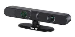
| − | File:Xtion.jpg | ASUS Xtion PRO. | + | File:Xtion.jpg | ASUS Xtion PRO (the PRO LIVE model includes a RGB camera). |
</gallery></center> | </gallery></center> | ||
| + | |||
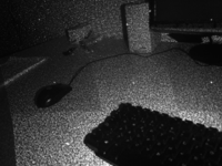
[[Image:Structured_light.png|thumb|center|200px|Infrarred light pattern (dots) projected by Kinect.]] | [[Image:Structured_light.png|thumb|center|200px|Infrarred light pattern (dots) projected by Kinect.]] | ||
| + | |||
=Point clouds= | =Point clouds= | ||
| Line 60: | Line 74: | ||
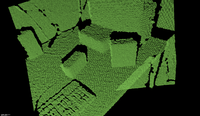
[[Image:Point_cloud.png|thumb|right|200px|Example of a point cloud.]] | [[Image:Point_cloud.png|thumb|right|200px|Example of a point cloud.]] | ||
| − | Depth sensors return 3D data in the form of a [ | + | Depth sensors return 3D data in the form of a [https://en.wikipedia.org/wiki/Point_cloud ''point cloud'']. A point cloud is a set of points in three-dimensional space, each with its own XYZ coordinates. In the case of stereo, ToF or structured light cameras, every point corresponds to exactly one pixel of the captured image. Optionally, points can store additional information, like color (if the sensor has a RGB camera that it uses to put texture on them). If you have background with 3D modelling software, then you must know that point clouds can be converted to triangular meshes with certain algorithms, but this is rarely done, and cloud processing is performed with the original set of data. |
| + | |||
| + | ==Point Cloud Library== | ||
| + | |||
| + | [https://en.wikipedia.org/wiki/Point_Cloud_Library Point Cloud Library (PCL)] is a project started in early 2010 by [https://en.wikipedia.org/wiki/Willow_Garage Willow Garage], the same robotics research company behind the [https://en.wikipedia.org/wiki/Robot_Operating_System Robot Operating System (ROS)] and OpenCV (and they also sell [http://www.willowgarage.com/robot/overview robots] like TurtleBot, too). The first version was [http://www.pointclouds.org/assets/pdf/pcl_icra2011.pdf fully introduced] in 2011, and it has been actively maintained ever since. | ||
| + | |||
| + | PCL aims to be an one-for-all solution for point cloud and 3D processing. It is an open source, multiplatform library divided in many [http://pointclouds.org/documentation/tutorials/walkthrough.php submodules] for different tasks, like visualization, filtering, segmentation, registration, searching, feature estimation... Additionally, it can be used to retrieve data from a list of compatible sensors, so it is an obvious choice for our tutorials, because you will not have to compile or install dozens of separate libraries. | ||
| + | Apart from Willow Garage, PCL is backed by [http://www.openperception.org/ Open Perception], a non-profit organization founded by Radu Bogdan Rusu, one of the most active developers of the library. I recommend you to read his very interesting [http://files.rbrusu.com/publications/RusuPhDThesis.pdf dissertation], written in 2009, which introduces and details many concepts and techniques that have been implemented into PCL. | ||
| + | =Conclusion= | ||
| + | |||
| + | Over the course of the next tutorials I will tell you how to install PCL in a Linux environment, how to retrieve point clouds from a sensor like Kinect or Xtion, and how to work with them for things like object recognition. I will keep it nice and easy, just like I want tutorials to be, and leave complex stuff aside (you can always search the original paper if you want to learn more about some technique). | ||
| Line 77: | Line 101: | ||
[[PCL/OpenNI tutorial 2: Cloud processing (basic)]] | [[PCL/OpenNI tutorial 2: Cloud processing (basic)]] | ||
| + | |||
| + | [[PCL/OpenNI tutorial 3: Cloud processing (advanced)]] | ||
| + | |||
| + | [[PCL/OpenNI tutorial 4: 3D object recognition (descriptors)]] | ||
| + | |||
| + | [[PCL/OpenNI tutorial 5: 3D object recognition (pipeline)]] | ||
[[PCL/OpenNI troubleshooting]] | [[PCL/OpenNI troubleshooting]] | ||
Latest revision as of 22:50, 1 November 2015
Go to root: PhD-3D-Object-Tracking
One of the most important fields of robotics is computer vision. A machine that is able to "see" its environment can have a lot of applications. For example, think of a robot in a production line that grabs some parts and moves them somewhere else. Or a surveillance system that is able to recognize how many people are there in a room. Or a biped robot making its way through a room, evading obstacles such as tables, chairs or bystanders.
For many years, the most common sensors for computer vision were 2D cameras, that retrieved a RGB image of the scene (like all the digital cameras that are so common nowadays, in our laptops or smarphones). Algorithms exist that are able to find an object in a picture, even if it is rotated or scaled, or that can retrieve motion data from a stream of video, and even perform 3D analysis to track the camera's position. All these years' worth of research is now available in libraries like OpenCV (Open Source Computer Vision Library).
3D sensors are available, too. The biggest advantage they offer is that it is trivial to get measurements about distances and motion, but the addition of a new dimension makes calculations expensive. Working with the data they retrieve is a lot different that working with a 2D image, and texture information is rarely used.
During the next tutorials I will explain how to get a common depth sensor working with a 3D processing library.
Contents
Depth sensors
3D or depth sensors give you precise information about the distance to the "points" in the scene (a point would be the 3D equivalent of a pixel). There are several types of depth sensors, each working with a different technique. Some sensors are slow, some are fast. Some give accurate, high-res measurements, some are noisy and low-res. Some are expensive, some can be bought for a hundred bucks. There is no "perfect" sensor and which one you choose will depend on your budget and the project that you want to implement.
Stereo cameras
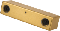
Stereo cameras are the only passive measurement device of the list. They are essentially two identical cameras assembled together (some centimeters apart), that capture slightly different scenes. By computing the differences between both scenes, it is possible to infer depth information about the points in each image.
A stereo pair is cheap, but perhaps the least accurate sensor. Ideally, it would require perfect calibration of both cameras, which is unfeasible in practice. Bad light conditions will render it useless. Also, because of the way the algorithm works (detecting corresponding points of interest in both images), they give poor results with empty scenes or objects that have plain textures, with few interest points. Some models circumvent this by projecting a grid or texture of light on the scene (active stereo vision).
I will not go into detail about the math involved with the triangulation process, as you can find it on the internet.
Time-of-flight
Time-of-flight (ToF) sensors work by measuring the time it has taken a ray or pulse of light to travel a certain distance. Because the speed of light is a known constant, a simple formula can be used to obtain the range to the object. These sensors are not affected by light conditions and have the potential to be very precise.
LIDAR
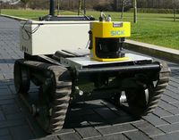
A LIDAR (light+radar) is just a common laser range finder mounted on a platform that is able to rotate very fast, scanning the scene point by point. They are very precise sensors, but also expensive, and they do not retrieve texture information. They have been used for decades in many different fields like meteorology, archaeology or astronomy. LIDAR devices can be mounted on satellites, planes or mobile robots. The data retrieved by a LIDAR has very high resolution, so some processing is needed in order to use it for real-time applications.
ToF cameras
A time-of-flight camera does not perform point-by-point scans like a LIDAR does. Instead, it employs a single pulse of light to capture the whole scene, once per frame. Thanks to that, they can work a lot faster, with some models topping above 100 Hz. The price to pay is a low resolution of 320×240 or even less. Depth measurements have an accuracy of about 1cm. ToF cameras cost less than LIDAR sensors, but we are talking about 4000 $ or so. Color information is not retrieved.
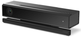
The new Kinect v2 is a ToF sensor that works at 512×424 internally, and it includes a 1920x1080 RGB camera.
Structured light
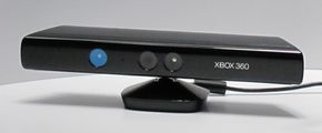
Structured light sensors (like Kinect and Xtion) work by projecting a pattern of infrarred light (for example, a grid of lines, or a "constellation" of points) on top of the scene's objects. This pattern is seen distorted when looked from a perspective different from the projector's. By analysing this distortion, information about the depth can be retrieved, and the surface(s) reconstructed.
The resolution and speed of these sensors are similar to common VGA cameras, usually 640x480 at 30 FPS (actually less because of the way this type of sensors work, Kinect uses 320x240 internally, the rest of the data is extrapolated to "fill the gaps"). Precision is similar to that of ToF cameras, 1cm more or less, with a maximum range of 3-6m, but they tend to have trouble seeing small objects. They are a lot cheaper than any other sensors, with a first generation Kinect now costing around 100 $, and hence they have become a lot popular in the last years. In the next tutorial, I will explain the installation and usage of one of these cameras.
Point clouds
Depth sensors return 3D data in the form of a point cloud. A point cloud is a set of points in three-dimensional space, each with its own XYZ coordinates. In the case of stereo, ToF or structured light cameras, every point corresponds to exactly one pixel of the captured image. Optionally, points can store additional information, like color (if the sensor has a RGB camera that it uses to put texture on them). If you have background with 3D modelling software, then you must know that point clouds can be converted to triangular meshes with certain algorithms, but this is rarely done, and cloud processing is performed with the original set of data.
Point Cloud Library
Point Cloud Library (PCL) is a project started in early 2010 by Willow Garage, the same robotics research company behind the Robot Operating System (ROS) and OpenCV (and they also sell robots like TurtleBot, too). The first version was fully introduced in 2011, and it has been actively maintained ever since.
PCL aims to be an one-for-all solution for point cloud and 3D processing. It is an open source, multiplatform library divided in many submodules for different tasks, like visualization, filtering, segmentation, registration, searching, feature estimation... Additionally, it can be used to retrieve data from a list of compatible sensors, so it is an obvious choice for our tutorials, because you will not have to compile or install dozens of separate libraries.
Apart from Willow Garage, PCL is backed by Open Perception, a non-profit organization founded by Radu Bogdan Rusu, one of the most active developers of the library. I recommend you to read his very interesting dissertation, written in 2009, which introduces and details many concepts and techniques that have been implemented into PCL.
Conclusion
Over the course of the next tutorials I will tell you how to install PCL in a Linux environment, how to retrieve point clouds from a sensor like Kinect or Xtion, and how to work with them for things like object recognition. I will keep it nice and easy, just like I want tutorials to be, and leave complex stuff aside (you can always search the original paper if you want to learn more about some technique).
Go to root: PhD-3D-Object-Tracking
Links to articles:
PCL/OpenNI tutorial 0: The very basics
PCL/OpenNI tutorial 1: Installing and testing
PCL/OpenNI tutorial 2: Cloud processing (basic)
PCL/OpenNI tutorial 3: Cloud processing (advanced)
PCL/OpenNI tutorial 4: 3D object recognition (descriptors)
